Biasing a Tube Amplifier
For Fixed Adjustable-Bias Amplifiers

Warning: The adjustments and processes described in this article require interacting with dangerous levels of voltage. Even unplugged, an amplifier can retain dangerous levels of charge. We encourage you to take extreme precautions when performing these adjustments or interacting with your amplifier. When in doubt, seek the help of a trained professional.
You can follow this process with our companion video on how to bias your amplifier here:
Required Tools:

- Matched Power Tubes - we recommend Apex Matched Tubes
- Multimeter - we recommend S-Z3220
- Bias Meter with probes - we recommend S-TBM4
- Small screwdriver - we recommend S-TXP600
- Basic hand tools - we recommend S-T311
- Dummy load or test speaker
- Speaker cable - we recommend S-H280
- Something to hold your hardware - we recommend S-T304
Whether you are replacing a worn out set or want to try a different brand of power tubes, there are a few things you will want to verify before installing the new set. Some amplifiers such as cathode biased amps are generally good to go without any adjustments but many amplifiers have a fixed bias. These amps require a bias adjustment for the tubes to operate properly. With a properly biased amp, the amplifier will work more efficiently and will accurately amplify the sound of the guitar, pedals, and preamp. An incorrect bias setting can result in crossover distortion, inefficiency, and can cause damage to the tubes and amplifier.

This guide will cover fixed adjustable bias amps. Fixed adjustable bias amps feature a trimpot for the bias adjustment. Check your model's manual to determine if this procedure applies to your amplifier.
Matched Tubes

Matched tubes are essential in vacuum tube power amps. Without a matched set, a proper bias will not be possible. This can result in one or more tubes not operating correctly, running too hot, or even red-plating which will damage the tube and possibly the amplifier. Apex Tube Matching® uses state of the art equipment designed and built specifically for matching tubes used in guitar and audio amplifiers. With a precision matched set from Apex®, you will be ready to accurately bias your amplifier. For increased bias stability we highly recommend the Apex Burn In® sets. These tubes are burnt in with a continuous identically high plate current for four hours prior to matching for maximum stability.
The Trim Pot
Typical Marshall-style trimmer mounted to the PCB

Typical Fender-style trimmer mounted to the chassis bottom

Other styles could also be used

In fixed adjustable bias amps, the bias is set using a trimpot. This potentiometer works similarly to a volume pot on a guitar but it controls the level of a negative voltage inside the amp rather than the volume or tone of the signal. Instead of adjusting the pot with a knob, the pot usually has a slot for a screwdriver. To access the bias trimpot, the amplifier usually needs to be disassembled.

This can require removing the chassis from the cabinet or if you are lucky you can simply remove a back panel on the amp. Check the manual and inspect the amplifier before removing any hardware to determine the correct way to access your amplifier trimpot.

Amplifier Voltages

Warning: For safety, make sure the amplifier is off and unplugged before attempting this. If the amp was recently in use, give it some time to cool down. Tubes can get very hot! Once you have taken these precautions, disassemble the amp to gain access to the internal parts. Place the amp or chassis onto a well-lit workspace.
Even with the amplifier unplugged and powered off, dangerous voltages can still be present in the circuit. Electrolytic capacitors can potentially hold a charge for indefinite periods of time. Always treat the internal circuitry as if it holds a lethal charge unless you know it to be safe. This involves avoiding contact with any internal components or wiring. Yes, it might look awesome in your amp, but do not touch it! If there is a situation where you absolutely need to touch a component, precautions must be taken. Referencing a schematic, identify the capacitors that would hold a charge. These are usually electrolytic capacitors in the power supply or connected to power elsewhere in the circuit but any capacitor could potentially hold a dangerous charge. Using a discharging tool, safely discharge all capacitors. Before making contact with the component, use a multimeter to take a voltage reading to ensure that no voltage is present.
Connecting the Bias Meter

Now that we have gained access to the internal circuitry of the amplifier, the bias meter should be connected. A bias meter is a device that can measure current in a tube amplifier. It uses a set of probes that are plugged into the tube sockets and the tubes are then plugged into the probes. This allows the meter to jump into the circuitry of the power amp without the need to disconnect any wires or components. The bias of the tube amp is measured in milliamps (mA) which are a unit of measurement for electric current. Our example amplifier has four power tubes all using octal sockets, so we will need four octal probes for our measurements. An amplifier with two tubes will only need two probes. While uncommon, an amp with a single output tube and a fixed adjustable bias would only need one probe.

Measuring Plate Voltage

With the bias probes and new tubes installed, we now need to set up a multimeter to measure the plate voltage. We will do this directly on the power tube sockets. For our example amplifier, we need to flip the chassis over. We use some sturdy wood blocks to hold the amplifier up and level when it is flipped over. Make sure the amplifier is in a steady position so it does not shift or fall over when working on it.

Looking at the inside of the octal sockets, there are some printed numbers on the socket associated with the pins. If your socket does not have these numbers you can count the pins using the key, which is the small notch in the center hole of the socket. Pin 1 is the first pin clockwise from the key.
Bottom View of Socket

Pin 3 is the plate (anode) for the following tubes:
- EL34
- 6CA7
- 6L6GC
- 6V6GT
- KT66
- KT77
- KT88
- KT90
- 5881
- 6550
- 7027
- 7591
Locate the pin that connects the plate voltage to the tube. In our case, we are using EL34 tubes so we will locate pin 3. We will connect the positive lead of our multimeter to this pin. Locate a good ground connection for the negative lead of the multimeter. Many people simply connect the negative lead directly to the chassis or to a conductive lug attached to the chassis. The cathode of the EL34 connects to ground in our amp so we will attach our negative lead there. We are using test leads with alligator clips. These are very useful since we can safely attach our test leads before applying power.

We will carefully prepare the amp so we can begin our measurements. Make sure the multimeter is set to the appropriate volts DC range. If your meter has a range that covers 300-600V, this should work for most amps. If you are unsure, set it to the highest setting and work your way down once you get a reading. Our meter is autoranging so we only need to set it to volts DC. Check the manual for your meter to determine which settings are required.
We will turn down all of the volume controls on the amplifier to zero and connect a load to the output of the amplifier. We will use a speaker for our output load.

Some techs will use a dummy load. As long as the load matches the output impedance and has a power rating greater than the amplifier power, it should be fine to use. We will not be using it for sound so do not worry about the quality of the speaker. Double check the connections making sure that no pins are bridged and double check that the chassis is securely positioned on the bench top. Be sure to keep hands and tools clear of the amplifier. There will be high voltages, often close to 500V, present in the circuit. Plug in the amp and turn on the power.

Once the tubes have warmed up we will disengage the standby switch to apply the plate voltage to the power tubes.

Some amps will not have this and the meter will start measuring the plate voltage as soon as the amp is on. As the tubes warm up this voltage might drift a bit so allow it to settle before beginning the bias adjustment. Our amplifier's plate voltage settled at 456.6V.

Calculating Bias Current
Now that we have our plate voltage reading, we will take this reading over to our bias calculator to determine our bias current:
Amplified Parts Bias Calculator
After typing in our plate voltage and selecting the tube type, we will now see some information on bias currents. There is also a lot of good information on that page showing how the calculator works if you are interested.
| Output Tube | EL34 |
| Max Dissipation | 25 W |
| Plate Voltage | 456.6 V |
| Recommended bias point for Class A/B amps | 70% |
| Recommended bias point for Class A amps | 90% |
| 60% Bias Point | 70% Bias Point | 80% Bias Point | 90% Bias Point | 100% Bias Point | 110% Bias Point |
|---|---|---|---|---|---|
| 32.85 mA | 38.33 mA | 43.80 mA | 49.28 mA | 54.75 mA | 60.23 mA |
We will be using the 70% bias point. This is a common setting for the bias. 60% is another common choice. You can always adjust the setting in the future so if you are unsure, 70% is a good choice for now. For EL34 tubes with a plate voltage of 456.6V, we see our bias point will be 38.33mA. Different tubes and different plate voltages will result in different bias points. We will now locate our bias adjustment trimpot and set it for 38.33mA using our bias meter.

Our bias trimmer is labelled on the PCB and has a nice feature, labels showing the direction to turn the trimpot to increase or reduce the bias current. This is somewhat uncommon so if your amp does not you simply turn the bias trimpot a little in one direction or the other to determine how to increase or decrease the bias.

For this part of the process, safety needs to be the main priority. We will keep our hands and tools clear of the circuitry in the amp. The metal of the screwdriver is conductive so our hand is kept only on the plastic handle. We are careful to only touch the screwdriver to the adjustment slot on the bias trimmer. Many techs will use the "One Hand Rule" when working on a live circuit. This involves keeping one hand in your pocket to avoid contact with a grounded surface, such as the chassis of the amp. We will make small adjustments to the bias trimmer, slowly move our hand away from the amp and then check the bias meter. We are repeating this process, making minor adjustments until the bias matches the bias point from the calculator.

When the bias point is finally set, we will observe it to make sure that it is not drifting. Small fluctuations are normal. We are only making sure it is not dramatically rising or falling. Depending on the tolerances of parts used in the amplifier, the bias might be slightly different for each tube. In these situations, set the highest number to the 70%.
This step is not necessary, but we have connected the amplfier to a scope so you can see the correct curve form as we get close to the correct bias point.

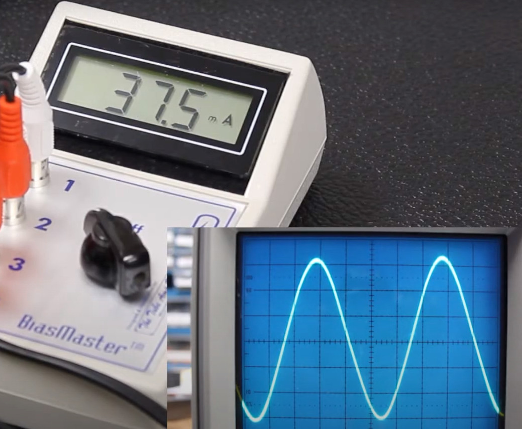
Compare this to the graph we saw earlier and you can see the process working!
When we are satisfied with the bias setting we will power down the amp and unplug it. The tubes will be extremely hot so we will allow them plenty of time to cool down before touching them. Once they have cooled down, we will remove the bias probes and replace each tube into its socket. Finally, we will carefully reassemble the amp keeping in mind that the capacitors might still hold charge if they have not been discharged manually.
With the amp fully reassembled it is time to plug it in and test out the new tubes. The power tubes are now biased correctly and the power amp should be amplifying the signal accurately and optimally providing the rich guitar tones that only a tube amp is capable of achieving. If you found this article helpful or interesting, be sure to explore out other tech articles. We have a variety of helpful tools, evaluations ranging from tubes to spring reverbs, as well as descriptions and diagrams of guitar and amplifier parts which are all free to access.