Amp Kit - Mod® Electronics, MOD102 guitar amplifier
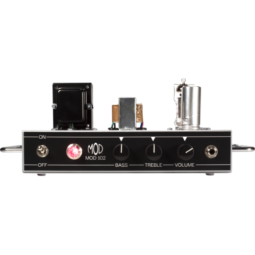
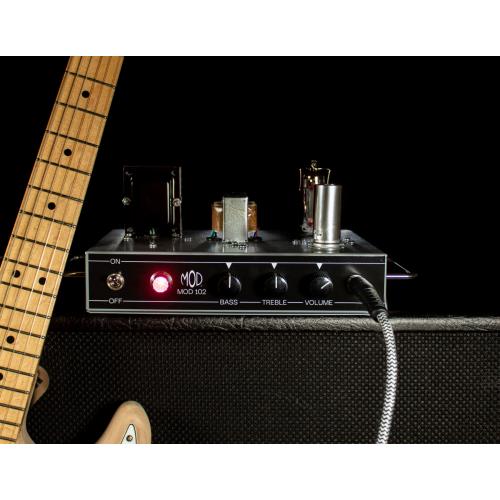
The Mod® Electronics MOD 102 is a great place to start for those interested in building their own tube amp. It is based on a classic American tube-circuit design combined with a British-style Class A output tube section. At low volume it produces a clean, chimey tone that moves into smooth overdrive at higher volumes. All parts are included along with a pre-drilled steel chassis, wire, and tubes (1 EL84 and 1 12AX7). Puts out at least 5 watts. The chassis layout is open for easy assembly using the clear, easy to follow instructions. You will need your own tools and solder.
MOD 102 Guitar Amp Kit Features:
- All Tube Design (solid-state diodes used only for full-wave rectification)
- 5W output power into 8 Ohm
- 1 channel
- Vintage channel controls: bass, treble and volume
- Vintage pilot lamp and screw-on jewel cover for power-on indication
- Output Impedance: 8 Ohm
- Tubes included: one 12AX7 (preamp), one EL84 (JJ Electronic brand)
- Hammond Mfg 269EX power transformer and P-T31 single-ended output transformer
- Cathode biased class A power tube operation (no bias adjustment needed)
- Point to point hand wiring using terminal strips
- Carbon film resistors
- Metalized polyester coupling caps
- Pre-punched steel chassis
- Assembled Kit Weight: 4.25 lbs.
- Assembled Kit Dimensions: 10" Width x 6" Depth x 5-⅛" Height
MOD 102 Instructional Features:
- Detailed, easy-to-follow instructions include high resolution computer drawings for parts list and every step of assembly
- Tips for soldering and wiring
- On-line technical support
5
SKU:
K-MOD102
Item ID:
001827
UPC/EAN:
609722127431
Brand:
Mod ElectronicsAnimus Series
Type:
| Height | 5.125 in. | ||
| Item Height | 8.5 in. | ||
| Item Length | 12 in. | ||
| Item Width | 10.5 in. | ||
| Length | 10 in. | ||
| Output Impedance (Zout) | 8 Ω | ||
| Output Power (POut) | 5 W | ||
| Width | 6 in. | ||
| Packaging Dimensions | 13 in. × 11 in. × 9 in. | ||
| Weight (Packaging) | 7.3348 lbs. | ||
| All Models | |
| All Models | |
| All Models | |
| All Models | |
| All Models | |
| All Models | |
| All Models | |
| All Models | |
| All Models |
My Project Lists
Specifications, Files, and Documents
Sound Samples:
Sound Sample01:20https://www.amplifiedparts.com/sites/default/files/associated_files/mod_102_sound_sample.mp3
Update Required To play the media you will need to either update your browser to a recent version or update your Flash plugin.
Questions? Contact us at [email protected], or give us a call at 480-296-0890
Customers who purchased this item also bought













Product Reviews
I have not completed assembly of the amp but I am having a very difficult time with the first filter cap portion. Very poor design. The wire that is included is awful. The ceramic sockets are of poor quality. So far I am going to have to purchase additional parts to upgrade the kit to a satisfactory level. I am hoping with some better qualty components and a bit of a redesign of the power section I will be able to complete assembly and that the amp will sound good.
This kit is extremely helpful for anyone starting out in electronics or already proficient at it. Plus this thing sounds great. I'm definitely buying another one or something along that line and start doing my own modifications. THANKS Amplified....
Great Kit and good customer service too. Five Stars
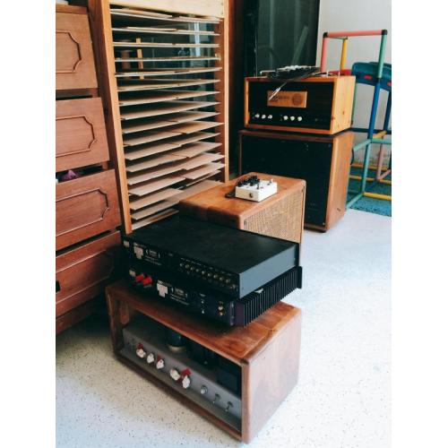
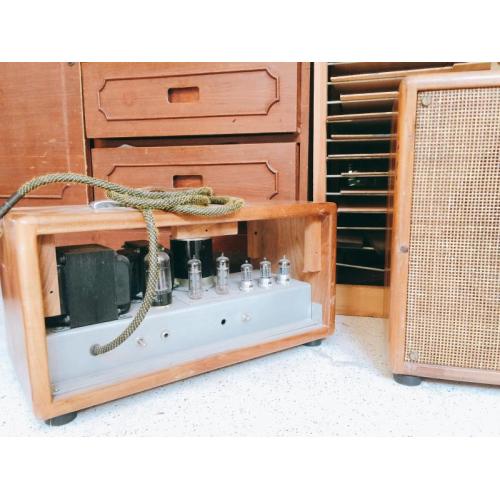
I just finished my build day before yesterday. I initially bought the MOD102 but then decided to buy the extra components for the MOD102+ since I was modding the build anyways and I wanted to get some more functionality out of it. Ive gotta say im glad i decided to build the MOD102+ instead. Sometimes designers add mods just for the sake of being able to say a product has more features but this is certainly not the case here. The "bright" settings frequency is dialed in perfectly and i find it very useful. It add a load of versatility in my opinion. I also seriously considered doing away with the mid resistor (6.8k) so i could just use a 25k mids potentiometer instead but with the other mods I had planned space was tight. Luckily i can say that the mid boost mod helps me cover just enough ground so that i dont feel like ill miss the versatility of an actual mids pot. Now for a couple of the mods i did unique to my build (i posted two pics of the amp so if they've been approved you should be able to see them on here). The first mod I did was to add an extra octal (8 pin) socket to the chassis so that i could also use this amp with a 6v6. I could have just left it at that and only plugged in the 6V6 or EL84 one at a time but I wanted to not have to switch them out constantly and i wanted each tube to be biased ideally rather than having to find a less than ideal compromise between the two so i put each tube on a cathode lift switch to select one tube or the other. So the 6V6 and EL84 are wired in parallel on all pins except the cathodes which run to a SPDT that connects only one cathode to ground at a time. I also had to find a good value for the cathode bias resistor and bypass cap for the 6V6 as the EL84 values wouldnt have worked properly. I ended up settling on a 470R 5W for the 6V6 bias resistor and a 25uf for the bypass capacitor. So far im very happy with those values. For the second mod (theres more but these two were the biggest) I changed up the cathode ground path a bit on V1 pin 8 so that i could add back in the negative feedback loop and put it on a switch as well. I modeled the NFB loop off of the "Champ Amp AA7 64" schematic and to bypass the loop i just bypass the 47 ohm resistor on the cathode of V1 pin 8 thats after V1 b's cathode resistor and capacitor (the 47 ohm isnt part of the MOD102+ schematic, it was part of the Champ Amp 64 schematic that was nessesary in order to add back the NFB loop). I even used the same resistor value for the NFB loop as the Champ Amp 64 which is a 2.7k (less resistance equals more NFB, more resistance equals less NFB). I think it might be cool to add a small toggle switch to the back of the amp and put the 2.7k NFB resistor and a 22k resistor on it so i can select NFB "High" or "Low" on the back of the amp. So from the front of the amp when you select NFB "ON" its either a lot or a little of NFB depending on where that toggle switch on the back is set. I still need to make my decals for the amp but im out of printer ink right now but ill get around to it eventually. As for the sound difference between the EL84 and 6V6 im really pleased with both of them and the differences are quite dramatic. The 6V6 is just like youd expect with more lows and highs and less mids. Its cleaner and fuller sounding but overall is quieter than the EL84 because 6V6's need more input signal to equal the same output as the EL84 but the 6V6 is still more than loud enough. If you wanted to do this mod and the volume mismatch bothered you there are a few ways you could compensate (attenuate the EL84 with a voltage divider/add masters for each tube, or boost the input but only on the 6V6 etc). The EL84 on the other hand has more mids, is louder and quicker to brake up. Both sound wonderful in their own way and i love having the option to use either. With all the good though there was bound to be some bad. Nothing big though. For example the push/pull volume pot is literally the worst push/pull volume pot ive ever experienced lol. The taper is completely shoved up at the upper end way more than most audio/logarithmic pots are (and there is zero volume at all until about a quarter of the way up on the volume which makes sense considering the wacky taper it has). And it has a lot of slop to it when turning or pushing/pulling it. It also feels completely stiff when turning lol. Its just all around a crappy pot which i really didnt expect when i bought it since it looks like it would be a great switch. I thought maybe i got a dud but apparently thats just how these specific push pull pots are. So i would highly recommend just using a regular A1M pot and using a toggle for the "turbo" function or sourcing a different pot which will be tricky but not impossible. For example ill be replacing mine with a Bourns A1M Push/Pull 3/8 shaft diameter that will work great with the only downside being i cant find it in a solid shaft variant so ill just cut some wood to go in between the slot on the shaft and use a regular set screw knob or pick up some brass splined to solid shaft adaptors. The other con I would say would be the way the off/standby/on switch is wired (or the way the on/off switch is wired if your building the MOD102). The reason its a con is because they designed it to switch the neutral wire rather than the hot wire. I reached out to Amplified Parts (who have been incredible through this whole build when i had questions btw) and asked them why they didnt design the amp the safer way which is to switch the hot wire. They told me it was because in such a small enclosure running the neutral wire was a trick amp builders used to use to avoid excess noise from having current so close to signal wires. And they are absolutely correct that theoretically this would be less prone to noise. But I still think you could get away with switching the hot wire if you do your layout very carefully (Amplifed Parts said just that in their response to me as well, so its up to you if you want to switch neutral and have it be less safe or switch hot and have to be extra careful with your layout to avoid possible noise/hum). Some Fender champs even switched both simultaneously so thats also an option. For now i wired mine to switch the neutral cause with all my mods noise was already a concern but the amp actually turned out to be dead quite when your on low to medium volume and the noise you get when your really cranking the amp isnt unbearable largely in part to the addtion of the artifical center tap mod that the MOD102+ incorporates (so if youre building the MOD102 at the very least pick up two more 100R resistors and do that mod cause its very effective at keeping the noise down). The last thing ill say is this. Earlier I ran my MOD102+ alongside my Marshall DSL100HR in a wet/dry type stereo setup and it was by far the best tone and most enjoyable playing experience ive had on an electric guitar. But i didnt build this amp because i needed a great amp. Ive been building pedals and guitars and restoring vintage tube radios/recieivers for a long time and this project has been my favorite out of all my builds (and there a quite a lot many of which im very fond of and use everytime i plug in my guitars). I wanted to build this amp because I wanted to expand my knowledge of tube circuits and this kit certainly did that for me. BUT, you could easily buy this kit and follow amplified parts/mod kits instructions and walk away not having learned much at all cause they really walk you through it all to the point that you really only need the proper tools and the ability to solder. So if you are building this amp to learn you should be aware that just following the instructions isnt likely to teach you in a meaningful way. I highly recommend if youre doing this kit to look up the Fender Champ schematics and really pick them apart. That is how youll actually learn something while doing this kit. A good way to walk away from this project having learned a lot is to modify the schematic. Not by blindly following someone's advice online but by thinking of a mod youd like to see in this amp and then going online and researching and asking questions etc. For the 6V6/EL84 switch mod i had to do just that. I found very little online about doing that mod and most of my info came from looking up similar schematics and staring at them for hours and looking up all the questions i had until i understood them. Having done that i absolutely feel like im walking away from this build significantly more knowledgeable on tube amps than i was when i started. If thats your goal then this kit is a great stepping off point. But there is also NOTHING wrong with wanting to just follow the instructions and end up with a great little amp. If thats your goal that by all means go for it! To each is own. I really enjoyed this experience and im certain it wont be my last amp build. In fact likely the first of many.
This is the first amp I have ever built and it was great. I have several years experience building pedals, this was a fun next step. The tone is great, very warm and dynamic. I would recommend this kit to anyone.
Great kit, fun to build. Took just a few hours from start to completion. Instructions are very high quality. I completed the build and then powered up without tubes to do voltage checks. When everything looked good I added the tubes and powered back up. Plugged in a Telecaster and started playing. Highly recommended if you are comfortable with building a project of this type.
This will be my third amp build, always quality parts and sounds great. Signal breaks up nicely when turned up. Used the Jensen Vintage Ceramic speaker in 2 of them, nice warm tone that compliments the circuit.
Great little amplifier! Sounds excellent and was fun to build. MODkits was also very helpful when I inevitably needed help troubleshooting a mistake I made. Would recommend this for anybody looking to build their first amp but I would strongly recommend you build a pedal first and practice your soldering skills. I have build several pedals and this was still a challenge.
I spent three evenings building the MOD102. The instructions are very easy to understand and the amp has a great Fender sound. I had one grounding issue that was easily fixed with a little help from tech support, which was excellent. If you're good at following step by step instructions and can solder well this is a fun little amp to build. Only small issue is the labels. They could stand an improvement.
I just finished this amp build and it sounds fantastic! I also just finished a Marshall 18 Watt clone and I have to say that the Mod102+ holds its own very nicely alongside the Marshall. In fact, I will probably use the Mod102+ for recording because it sounds amazing at lower volumes (the Marshall is loud AF). Honestly, if I were only going to build one of them today, it would be the Mod. I'm blown away by the tone! Great kit with excellent instructions. Great bang for the buck. The parts all seem to be top quality. I love the old style cloth solid core wire, too. I find it much easier to work with than modern stranded wire. The labels are a bit lame but I covered them with packing tape as suggested before cutting them out and they look fine. If you're thinking about building an amp, build this one.